

Maximum Scalability!


Discover the Five Superpowers of the Zero8 Product Family!
Benefit immediately from maximum efficiency, contact reliability, signal protection, speed, and robustness.
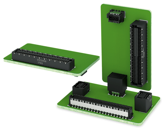
The Zero8 product family from ept has been specially developed for demanding industrial applications and offers maximum scalability: You can adapt types, stack heights, and pin counts to suit your individual requirements. The socket and plug are currently available as mid-profile and low-profile types and will also be available as high-profile and angled versions in the future. Due to the different heights, Zero8 connectors can be used to achieve board-to-board distances from 6.00 mm to 21.00 mm – a variable number of pins (between 12 and 80) can be requested.
But that’s not all. You also have a choice when it comes to shielding. Do you want both sides of the connector pair with or without shielding? Or perhaps just one side with shielding? The decision is yours – all Zero8 connectors are always compatible with each other and can be combined as you wish, either with or without shielding.


Superpower
EFFICIENCY
All Zero8 connectors feature a space-saving pitch of 0.8 mm between contacts so the minimum possible space is occupied on the PCB. Despite the small pitch spacing, the contacts are mated together on the smooth surface and not on the rough punching edge. This ensures the contacts are significantly more resistant to abrasion, for example, during micromovements.
Zero8 is available with 12, 20, 32, 52, or 80 contacts to ensure maximum flexibility in your application. The connector features two rows; for example, a 12-pin connector has six contacts in a row. If required, derivatives with a special number of pins can also be manufactured, for example, for larger clearances and creepages.
You also have a choice when it comes to shielding! Do you want both sides of the connector pair with shielding or without? Or perhaps just one side with shielding? The decision is yours – all Zero8 connectors are always compatible with each other and can be combined as you wish, either with or without shielding. In the shielded types, the solder terminals of the contacts are located below the connector, whereas in the unshielded types they are located on the sides to enable AOI inspection during the processing stage.
The straight types low, mid, and high allow board-to-board distances to be implemented in any size from 6 to 21 mm. The minimum possible board-to-board distance is achieved by plugging the connector all the way in to the stop position. The plug and socket can be plugged to a variable extent within a range of 1.5 mm to achieve the maximum possible board-to-board distance. The remaining 0.8 mm ensures secure contacting (absolutely secure mating).
Combining the angled type with the straight type makes it possible to arrange the PCBs at an angle of 90 degrees to each other, for example, for backplanes with daughter cards. Combining two angled types allows two PCBs to be arranged side by side at an angle of 180 degrees. All this is possible with or without shielding and in the pin number variants 12, 20, 32, 52, or 80 contacts to ensure maximum flexibility in your application.


For further information, please visit our website www.ept-connectors.com


Superpower
CONTACT RELIABILITY
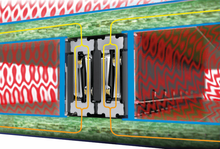
ScaleX – this brand stands for robust contact technology in a variably scalable connector system. It was specially developed to combine a high degree of mechanical robustness with outstanding high-frequency properties. This combination is unique within the world of PCB connectors.
Each pair of contacts consists of two blade contacts and two spring contacts. This redundancy not only leads to maximum contact reliability, particularly in demanding environments involving shock and vibration, it also ensures that your application is extremely durable and reliable. In addition, all contacting takes place on the smooth side of the plating and not on the rough punching edge as is the case with many other miniaturized connectors.
Redundancy in all contacts as well as contacting only on smooth, rolled surfaces results in exceptionally high resistance to shock and vibration. Zero8 connectors have been thoroughly tested and qualified according to the IEC 60512 standard. We would be happy to provide you with our detailed test reports.
Each mated contact pair of socket and plug has an overmating range of at least 0.8 mm. This corresponds to the distance from the contacting point to the contact tip, that is, the point at which there would no longer be any contact. This overmating range of at least 0.8 mm ensures correspondingly high tolerance compensation and therefore maximum security in every application. When plugging from plug to socket up to the stop, the overmating range increases to up to 2.3 mm per contact pair.
Zero8 contacts are designed to ensure secure contacting even after 500 mating cycles, including under the influence of temperature cycles and corrosive gas. Even if contacts are not mated 500 times, mating cycles are a suitable criterion for determining the extent to which connectors remain functional under multiple temperature cycles or vibration (“fretting corrosion”).


For further information, please visit our website www.ept-connectors.com


Superpower
SIGNAL PROTECTION
Providing shielding on both sides was a key focus when developing the Zero8. This guarantees an interference-free data transfer rate, as is required for many applications such as Industry 4.0 or IoT. The shielding material used is especially suitable for high electromagnetic compatibility requirements.
The shielding plates are designed with a large surface area and few interruptions, which ensures the greatest possible protection. In addition, the high number of contact points between the shielding plate and the PCB enables an optimal discharge of interference currents. For example, for a 20-pin connector, there are a total of five solder connection points to the PCB for a shielding plate over a length of 8 mm.
The influences of the electrical and magnetic field strength were first simulated and then checked by means of test trials during extensive tests carried out in a specialized laboratory. The results obtained are extremely good and can be made available if required. One of the main measurement results revealed that a coupling inductance of max. 10 pH could be achieved with Zero8 connectors.
You also have a choice when it comes to shielding! Do you want both sides of the connector pair with shielding or without? Or perhaps just one side with shielding? The decision is yours – all Zero8 connectors are always compatible with each other and can be combined as you wish, either with or without shielding. In the shielded types, the solder terminals of the contacts are located below the connector, whereas in the unshielded types they are located on the sides to enable AOI inspection during the processing stage.


For further information, please visit our website www.ept-connectors.com


Superpower
SPEED
Zero8 connectors meet the requirements of PCI Express Gen. 4 and Industrial Ethernet specifications, as are required for many applications such as Industry 4.0 or IoT. In addition to insertion loss, Zero8 performs very well when it comes to return loss and crosstalk.
Zero8 connectors are ideal for applications with a data transfer rate of up to 16 Gbps. Thanks to its excellent insertion loss properties, Zero8 can even be used for applications up to 25 Gbps. This outstanding suitability is combined with an extremely robust and resistant contact system for demanding environments such as shock, vibration, or noxious gas – a unique combination.
The double-sided shielding concept guarantees interference-free, highspeed transmission in industrial environments. The shielding concept reliably dissipates interference currents by means of multiple contacting on both PCBs. It protects the connector from electromagnetic interference (interference sink) and also protects adjacent components if the connector acts as a source of interference.
Zero8 was first thoroughly simulated with regard to its RF properties and then examined in test trials. Informative test reports and SI models are available for simulations in your application.


For further information, please visit our website www.ept-connectors.com


Superpower
ROBUSTNESS
Zero8 has been designed in such a way that the contacts will not be damaged even if operated incorrectly. The contacts are concealed in the insulator material and are therefore optimally protected against possible mechanical influences such as touching. This ensures the highest possible security for your application.
The polarization built into the insulator material prevents faulty mating due to twisting of the connectors. This means that the plug and socket can only be plugged together if they are aligned in a defined direction. In addition, distinct guiding elements in the insulator material help to make the mating process secure.
Two board locks per connector are soldered to the PCB and ensure mechanical relief of the signal contacts. This prevents signal contacts from tearing off the solder joint when the plug and socket are disconnected from each other.
Inclined insertion surfaces at the edge of the insulator material allow the plug and socket to compensate for an offset of up to 0.7 mm during the mating process. The blade and spring contacts are guided towards each other during the mating process in such a way that secure contacting of the contacts is achieved and incorrect plugging is prevented.
When mated, the socket and plug can tolerate a mutual displacement of up to 0.4 mm. This gives you a great deal of freedom when considering tolerances in your applications. It also makes it possible to place multiple connector pairs on a PCB without losing any contact reliability.


For further information, please visit our website www.ept-connectors.com


